
The mold usually has only the cavity part and no punch. The mold surface generally does not need to be hardened. The blow pressure borne by the cavity is much smaller than that of injection molding, generally 0.2~1.0MPG, and the cost is low.
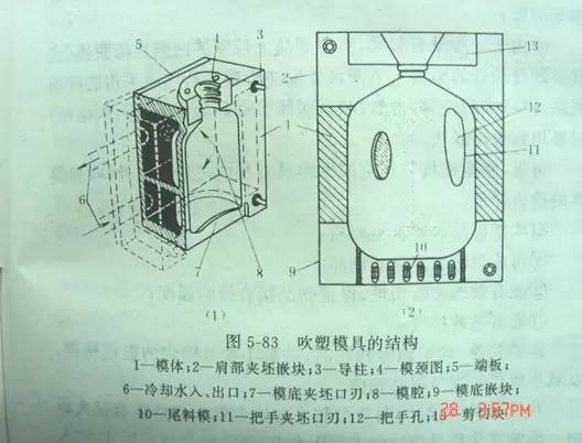
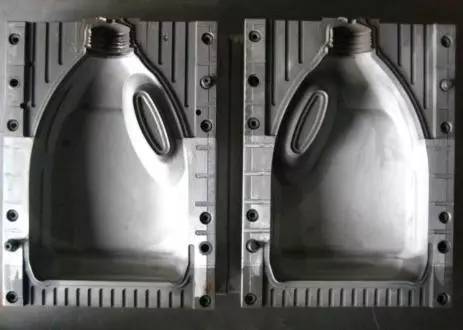
Blow mold structure diagram
Mold material
Generally, aluminum alloy is used for manufacturing, and beryllium copper or copper base alloy is also used for corrosive rubber materials such as PVC and POM. For molds with higher service life requirements, such as blow molding engineering plastics ABS, PC, POM, PS, PMMA, etc., stainless steel is required to be used to make molds.
mould
Key points of mold design
Parting surface
Generally, it should be placed on the symmetry plane to reduce the blowing expansion ratio. For example, for elliptical products, the parting surface is on the long axis, and for giant products, it passes through the center line.
Cavity surface
PE material should be slightly rough, and the surface of fine sand is conducive to exhaust; For blow molding of other plastics (such as ABS, PS, POM, PMMA, NYLON, etc.), the mold cavity generally cannot be sandblasted, and the exhaust slot can be made at the parting surface of the mold cavity, or the exhaust hole can be made on the mold cavity, and the diameter of the exhaust hole on the general mold cavity φ 0.1~ φ 0.3, length 0.5~1.5mm.
Cavity size
The shrinkage rate of plastics should be considered in the design of cavity size. For details, please refer to common plastic shrinkage rates.
Cutting edge and tailing groove
Generally, for blow molding engineering plastics and harder plastics, the cutting edge should be made of materials with good wear resistance, such as beryllium copper, stainless steel, etc. For LDPE, EVA and other soft plastic products, general aluminum alloy can be used.
The cutting edge should be selected with reasonable size. If it is too small, it will reduce the strength of the joint. If it is too large, it can not be cut and the clamping edge at the parting surface is large. However, a tailing groove is opened below the cutting edge, and the tailing groove is designed to be an included angle. When cutting, a small amount of melt can be squeezed into the joint, thus improving the strength of the joint.
Injection blow mold
The design is different from the extrusion blow molding. The main difference is that the injection blow mold does not need to cut the edge and tailing groove. The blank design of the injection blow part is very important, which directly affects the quality of the finished product.
Injection mold - parison design principles
1. Length, diameter and length ≤ 10/1
2. Blowing expansion ratio 3/1~4/1 (ratio of product size to parison size)
3. Wall thickness 2~5.0mm
4. According to the shape of the product, the wall thickness is thicker where the blowing ratio is large, and thinner where the blowing ratio is small.
5. For elliptical containers with an ellipse ratio greater than 2/1, the core rod shall be designed as an ellipse. For elliptical products with an ellipse ratio less than 2/1, the round core rod can form an ellipse container.
Blowing rod design
The structure of the air blowing rod is determined according to the mold structure and product requirements. Generally, the selection range of the hole diameter of the air intake rod is:
L<1: aperture φ one point five
4> L>1: aperture φ six point five
200>L>4: aperture φ 12.5 (L: volume, unit: liter)
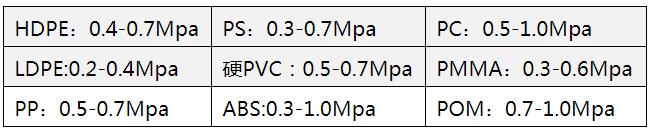
Air pressure of common plastic blow molding
Post time: Mar-22-2023